Abstract
The electrochemical discharge machining (ECDM) process is a hybrid of electric discharge machining and electrochemical machining. It was developed to overcome the limitations of other machining technologies on the micromachining of non-conducting materials. The performance of the process depends on various parameters. In this review article, the implications of input parameters on machining performance have been covered in detail. It is observed that various input parameter levels give different rate and quality of machining. A higher applied voltage and electrolyte concentration give a higher material removal rate but has adverse effects such as overcutting and heat-affected zone. The optimum process parameters for better material removal rate and surface quality have been discussed. The ECDM technique has undergone numerous modifications to meet various machining needs. The main ECDM process variants have been thoroughly examined. A wide variety of non-conducting materials, including glass, ceramics, and reinforced composites, have been successfully machined using the ECDM technique. The applications of the ECDM process have been examined and addressed. Potential future research directions and present advancements have also been presented.
Nomenclature
| ECDM | Electrochemical Discharge Machining |
| AJM | Abrasive Jet Machining |
| AWJM | Abrasive Water Jet Machining |
| USM | Ultrasonic Machining |
| EBM | Electron Beam Machining |
| LBM | Laser Beam Machining |
| HAZ | Heat Affected Zone |
| EDM | Electric Discharge Machining |
| ECM | Electrochemical Machining |
| MRR | Material Removal Rate |
| UA-ECDM | Ultrasonic Assisted Electrochemical Discharge Machining |
| G-ECDM | Grinding Assisted Electrochemical Discharge Machining |
| MF-ECDM | Magnetic Field Assisted Electrochemical Discharge Machining |
| MHD | Magneto Hydro-dynamic |
1. Introduction
Materials like quartz, glass, glass fibre-reinforced plastics, ceramics, and other composites are electrical and thermal non-conductors having a wide range of engineering applications. These materials have peculiar properties like high melting temperature, high hardness, thermal and electrical insulation, and low chemical reactivity. Some advanced ceramics are preferred over conventional materials in aerospace, electrical, and electronics fields as they require high corrosion resistance, high hardness, high compressive strength, and high thermal shock resistance. The hard and brittle nature of these materials makes the machining of these materials strenuous and expensive by conventional machining processes. Advanced machining processes like abrasive jet machining (AJM), abrasive water jet machining (AWJM), and ultrasonic machining (USM) have issues such as poor surface finish and dimensional inaccuracy. The surface roughness generated during micromachining of glass using these processes are in the range of 0.7 to 1.5 μm [1–3]. While in electrochemical discharge machining (ECDM) of glass, the surface roughness was found to be less than 0.1 μm [4]. Beam technologies like electron beam machining (EBM) and laser beam machining (LBM) have limitations of low μm aspect ratio and generation of the heat-affected zone (HAZ). The HAZ width was lower in ECDM, 40 μm [5], compared to 100 μm in the LBM [6]. Electric discharge machining (EDM) and electrochemical machining (ECM) are used for machining micro features on hard and brittle materials with high accuracy. But they have a limitation that they can only machine electrically conducting materials. ECDM is the hybridization of EDM and ECM that provides a solution to many of the shortcomings of these processes.
More studies and advancements are being made in the field of ECDM-based micromachining of materials. Sharma et al [7] successfully performed through-hole by micromachining of alumina using a combined pulse feed approach in ECDM. There have been several productive studies on micromachining of conducting [8] and non-conducting materials as well [9, 10]. Wüthrich et al [11] used vibration assisted tools to enhance MRR. Geometrical improvement to machined micro-holes on quartz was reported using an adaptive tool system in ECDM [12]. Nguyen et al [13] conducted experiments to fabricate microstructures in quartz material. Fabrication of micro-channels on quartz material [14], micromachining, and micro grinding on soda-lime glass [4] are all possible with ECDM process. The applications of ion transport in micro-nanofluidic systems were studied by Han et al [15, 16]. Figure 1 and figure 2 are images of micromachining on non-conducting materials using ECDM process.
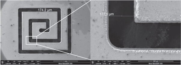
Figure 1. Microstructure on a 300 μm thick glass workpiece [27]. Reprinted from [27], Copyright (2017), with permission from Elsevier.
Download figure:
Standard image High-resolution image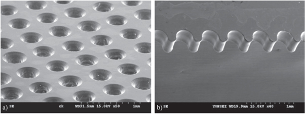
Figure 2. (a) Array of micro-holes [28]. Reprinted from [28], Copyright (2010), with permission from Elsevier, (b) Semi-circular 2D contours machined on a 400 μm thick soda-lime glass [29]. Reprinted from [29], Copyright (2011), with permission from Elsevier.
Download figure:
Standard image High-resolution imageThe tool materials commonly used include tungsten, tungsten carbide, stainless-steel, high-speed steel, copper, brass, and diamond embedded. The most widely used electrolytes are NaOH and KOH. Ceramics, borosilicate glass, soda-lime glass, quartz, pyrex glass, optical glass, and reinforced polymers are among the materials used for workpieces that are processed by ECDM machining.
There are many variations to the ECDM process which cater to different machining requirements. Electrochemical discharge drilling [17], wire electrochemical discharge machining [18], electrochemical discharge micro-milling [19], lathe-type electrochemical discharge machining [20], electrochemical discharge micro-grinding [4], and die-sinking electrochemical discharge machining [21] are some of them. Numerous studies are being conducted on the hybridization of ECDM with other processes. Some of them are electrochemical discharge abrasive drilling [22], ultrasonic-assisted micro-ECDM process [23], magnetic field assisted micro-ECDM process [24], magnetic field assisted traveling wire ECDM [25], and powder mixed micro-ECDM process [26].
The current study reviews literature from the past years on ECDM. All the topics starting from early developments to effects of process parameters, variants, and applications of ECDM are discussed in detail. The areas lacking developments and possible research areas are also discussed.
2. Historical developments
The first report on ECDM was published in 1968 by Kurafuji and Suda [30] of Japan, and the authors called it the process of electrical discharge drilling. The study examined the impact of tool-electrode material and the chemical composition of the electrolyte on machining parameters and demonstrated that it is possible to drill micro-holes in glass. There were many arguments on the similarities of the ECDM process with ECM and EDM. In 1973, Cook et al [31] published a report in which the author showed a relevant difference between the process given by Kurafuji and Suda [30], ECM, and EDM. They also named the process discharge machining of non-conductors. The authors claimed the process could be applied to a wide range of non-conductive materials.
In 1985, Tsuchiya et al [32] developed a new variant using a wire as a tool electrode. They showed that materials like glass and ceramics could be cut using this variant and named the process electrochemical discharge machining. In 1991, Jain et al [18] further developed this process and discussed the similarity with electrochemical arc machining. The application of ECDM in the field of MEMS was made in the 1990s. In 1996, Ghosh et al [33] defined how the machining process and electrochemical discharge phenomena are linked with a theoretical model.
The chemical effect in material removal mechanism was first discussed by Yang et al [34] in 2001. The authors described the method of material removal as a high-temperature etching process. More detailed studies on the chemical aspect of material removal mechanism were done by Fascio et al [35]. In 2005, Wuthrich et al [36] published the first review paper on ECDM. The review was focused on electric discharge phenomenon, chemical machining, and thermal machining. The influence of these phenomena on MRR was also discussed.
In 2006, Kim et al [37, 38] showed the effects of pulsed voltage on HAZ formed during micro-drilling. In the same year, Yang et al [38] discussed the use of abrasive mixed electrolytes. The authors reported improved surface roughness, overcut, and reduced slit expansion and discharge energy while adding SiC abrasive particles to the electrolyte. In 2008, there were developments in ECDM to be used in nanotechnology [39]. Machining of 3D microstructures was an advancement in the applications of ECDM, which was demonstrated by Cao et al [19] in 2009. In 2011, Yang et al [40] overcame the problems like high machining time and high entrance diameter in high aspect ratio drilling by using a spherical tool electrode. The developments of ECDM hybrids were observed from 2010 s. A study on magnetic field assisted ECDM was reported in 2010 [24]. Studies on grinding assisted ECDM [41] and ultrasonic assisted ECDM [42] were reported in the years 2013 and 2017, respectively. Use of laser assisted ECDM was reported in 2020 [43]. The timeline of developments in ECDM is summarised in figure 3.
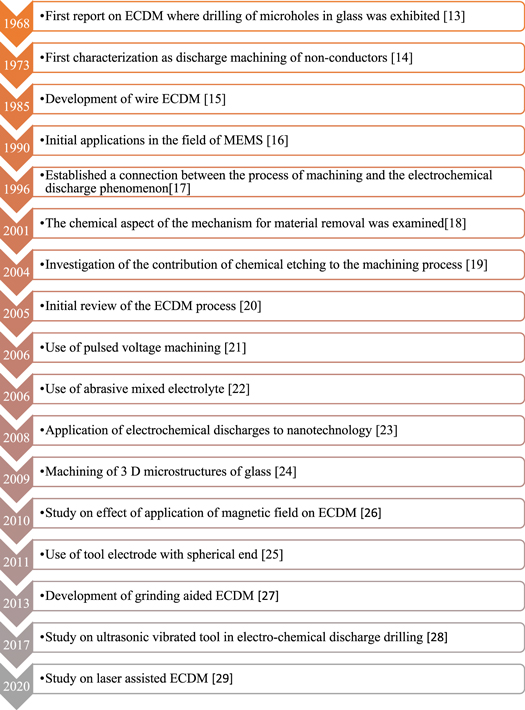
Figure 3. Timeline of developments in ECDM.
Download figure:
Standard image High-resolution image3. Process mechanism
One of the initial studies on process mechanism of ECDM process was by Basak et al [33]. The authors developed a theoretical model for mechanism of spark generation and validated it experimentally. Current flow through electrode causes hydrogen gas generation at cathode, and oxygen gas at anode. The bubbles form, grow in size, get detached from cathode, and move upwards when it crosses the critical size. The resistance increases, and this leads to ohmic heating. The number of nucleation sites increases and bubbles coalesce to form a blanketing effect over tool electrode. Spark discharge occurs when tool electrode is covered by gas film and current drops to zero. A schematic diagram of ECDM setup and spark discharge is shown in figure 4. Workpiece kept in the vicinity will be melted by the temperature developed due to transfer of energy from sparks. The molten material is removed by mechanical shock due to sudden phase change and electric shock due to discharge [44]. Kulkarni et al [45] have observed that the discharge is a discrete phenomenon. Workpiece shows signature of discharges, and discharge affected region can be seen as a circular zone.
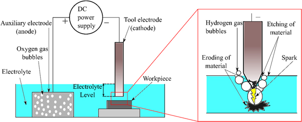
Figure 4. Schematic diagram of ECDM.
Download figure:
Standard image High-resolution imageIn reverse polarity ECDM, the material removal is due to melting, vaporization, and chemical reaction. Tool wear, in reverse polarity ECDM, is higher due to chemical reactions, and a crater is also formed on the tool electrode. It is useful in machining quartz as the chemical reaction causes dissolution of quartz in NaOH [46].
4. Effects of various process parameters
ECDM process has various input process parameters which have different levels of influence on the machining. Properties of electrolyte, applied voltage, and tool electrode and their effects on material removal rate (MRR) and machined surface have been discussed in this section.
4.1. Electrolyte
The electrolyte is one of the most influential parameters in the ECDM process. It has many functions, such as removal of debris from the machining zone, electrochemical etching, and generating gas bubbles for the formation of the gas film. A strong electrolyte solution that is acidic, neutral, or basic is recommended as it gives maximum sparking and bubble formation [47]. Classification of electrolyte along with commonly used electrolytes is given in figure 5.
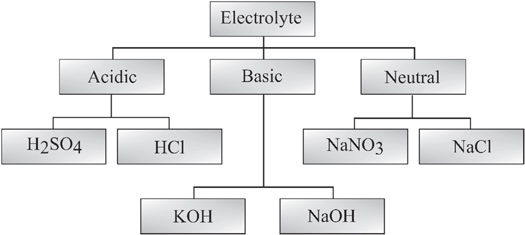
Figure 5. Classification of electrolytes used in ECDM.
Download figure:
Standard image High-resolution imageA higher concentration greater than 20 wt% is required for higher erosion and thermal discharging as it gives higher ionization and deionization. While machining soda lime glass, KOH gives better MRR than NaCl [48]. NaOH gives 40% better MRR and 36% lower tool wear rate (TWR) while machining soda lime glass than NaNO3 [49, 50]. NaOH has higher etching action and therefore gives a higher depth of cut than NaCl [51]. Mixed electrolytes have been found to have 20% higher MRR, 23% higher depth of cut, and 13% lower overcut at 25 wt % concentration than their parent electrolytes [52]. A mixture of KOH and NaOH has lower critical voltage [52] and higher conductivity [53] but produces irregular microfeatures at higher concentrations due to highly reactive KOH [54]. Better surface quality is achieved with acidic electrolytes like diluted H2SO4, which do not produce any insoluble reaction products. The surface quality is better because reaction products are not deposited on the surface. Electrolyte conductivity is decreased and dissolving is hampered by the insoluble reaction products. HCl causes non-uniform surfaces as a result of chloride-induced pitting corrosion [55]. Low conducting salt solutions as an electrolyte shows least surface roughness [56] and higher tool wear [57].
In a study using glycol-based electrolytes, the surface produced has good quality with surface roughness of 0.2 μm, and no recast layer. Large bubbles are formed in glycol-based electrolytes, forming stable gas film. Also, there is no oxygen gas precipitation on the workpiece surface eliminating any uneven trans-passive film formation [58].
Basic electrolytes have better performance than acidic and neutral electrolytes. Basic electrolytes give higher MRR through electrochemical action. Although, precautions must be taken against the toxic fumes produced by basic electrolytes while machining.
4.1.1. Electrolyte concentration
The electrolyte concentration is an important parameter in ECDM process as it has effects on output parameters of machining. MRR, average surface roughness, and kerf width increases with the increase in electrolyte concentration from 200 g l−1 to 250 g l−1 and then decreases with a further increase in concentration [59]. This is because the specific conductance of NaOH increases when concentration changes from 200 g l−1 to 250 g l−1 and then decreases with any further increase in concentration [21]. The improvement in MRR at higher concentrations can be attributed to enhanced electrochemical reaction between electrodes, producing more bubbles at the sparking zone and generating more sparks [60]. Higher electrolyte concentration results in deeper microfabrication with up to 47% improvement in depth as concentration changes from 15 wt% to 30 wt% NaOH [61]. A concentration of 20% to 40% is recommended for better machining while using KOH as an electrolyte, and no machining occurs at a concentration of less than 10% [48].
The variations in electrolyte concentration also changes the viscosity and thermal conductivity of the electrolyte. Electrolyte viscosity is the most significant parameter influencing micro-channel texture [62]. An increase in concentration from 10 wt% to 40 wt% NaOH changes the surface texture from branched feathery-like to a smooth spongy (porous) texture [63]. Kolhekar et al [64] found surface wrinkling near the perimeter of the hole and lower surface hardness at lower electrolyte concentrations. An increase in electrolyte concentration increases the hole taper, entrance diameter, and exit diameter of the micro-hole [65]. The straightness of the machined slits improved at higher electrolyte concentrations, as the electrolyte provides adequate heat to remove the material from work surface and removes edge chipping. The straightness deteriorated at concentration higher than 20% due to high thermal energy in machining zone [66]. According to Mallick et al [67], 20 wt% NaOH solution gives lower HAZ due to continuous sparking, and 30 wt% NaOH solution gives higher HAZ due to violation of sparking at higher conductivity.
Electrolyte concentration should be chosen based on applications. Higher electrolyte concentration gives higher MRR along with adverse effects like HAZ, overcut, and tapering. If better surface finish is the desired outcome over MRR, lower electrolyte concentration should be used.
4.1.2. Particles mixed in the electrolyte
Particles like surfactants or conductive powders are mixed in an electrolyte to enhance their performance during machining. A study on graphite powder mixed with NaOH shows reduced surface cracks and improved surface roughness [26]. Graphite concentration up to 1.25% in NaOH improves the MRR. When the concentration of graphite is increased above 1.25%, the MRR reduces because of the electrochemical discharge limitation as the free movement of electrons is restricted [68]. Kuo et al [69] conducted a comparative study on traveling wire ECDM (TW-ECDM) performance with and without SiC additives in the electrolyte. The result shows that increasing SiC concentration up to 5 wt% reduced surface roughness. Any further increase in the concentration increases the surface roughness, as excessive powder causes obstruction to electric discharge. Adding SiC powder also reduces slit expansion as it increases the critical voltage and reduces the discharge energy [38]. ECDM with Cu and Al2O3 nano electrolytes gives higher depth of cut. The nano electrolytes improve the hole depth by up to 20% but also increases the entrance overcut by up to 8% [70].
Adding surfactants to the electrolyte reduces the surface tension and therefore produces thinner gas films. Micro-channels with high surface quality, low HAZ, and high MRR have been produced using either anionic surfactant Sodium dodecyl sulphate (SDS) or cationic surfactant Cetyltrimethylammonium bromide (CTAB) [71]. SDS gives less taper and better-quality holes. It also increases the machining speed but forms an oversize hole [63]. Various particles added to electrolyte and their influence on machining is summed up in table 1.
Table 1. Effect of various particles mixed in electrolyte.
| References. | Type of electrolyte | Influence on machining |
|---|---|---|
| [26] | Graphite powder mixed with NaOH | Reduction in critical breakdown voltage. |
| [69] | SiC powder mixed with KOH | Abrasive and polishing effect enhances surface quality. |
| [70] | Copper nano particles with NaOH | Enhanced thermal conductivity up to 50%. |
| [70] | Al2O3 nano particles with NaOH | Enhanced thermal conductivity up to 20%. |
| [71] | CTAB mixed with NaOH, KOH | Reduce surface tension and critical voltage. |
| [71] | SDS mixed with NaOH, KOH | Improved machining depth. |
It is established that surfactant mixed electrolytes have lower surface tension, and formation of thinner gas films. This enables uniform sparking and better surface finish. Conducting particle powder can be used to improve electrolyte conductivity.
4.1.3. Electrolyte flow
The electrolyte flow influences the ECDM process by bringing fresh electrolytes to the machining zone and removing debris. The surface quality of deep holes in ECDM is limited due to vaporization of electrolytes and its improper replenishment in the machining zone. Arya et al [72] used a pressurized flow system for continuous replenishment of the electrolyte in the machining zone which gave higher depth and lower entrance diameter of micro-holes. Injection of pressurized electrolyte through hollow tool electrode, as shown in figure 6, improves the hole depth up to 70%. Increasing the injection pressure improves the electrolyte flow and enhance the hole diameter [73]. Super high-pressure interior flushing up to 10 MPa gives high machining speed and good surface quality. The high pressure allows the removal of debris from the narrow machining zone and improves the MRR [74]. Kuo et al [75] studied titrated electrolyte flow in ECDM process. Drop-by-drop flow ensures constant concentration of electrolyte and steady gas film. The titrated flow gives good surface quality and also reduces electrolyte consumption.
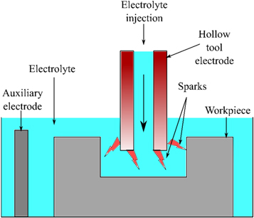
Figure 6. Electrolyte flow through hollow electrode.
Download figure:
Standard image High-resolution imagePressurized electrolyte flow through hollow tool electrode can be used to enhance deep hole drilling. Pressurized flow ensures electrolyte presence at deep holes while machining. It also enhances the debris removal from machining zone through better electrolyte flushing.
4.1.4. Electrolyte level
Electrolyte level is the depth up to which tool is immersed from electrolyte surface. According to Rusli et al [23], electrolyte level affects the workpiece and tool electrode resistance. Low electrolyte level increases thermal energy and enhances wettability of electrode. This generates a high bias current which gives good surface integrity and lower MRR during machining [13]. Higher level of electrolyte exposes more area of tool, increasing the buoyant force of the gas bubbles and reducing the gas bubble stability [76]. When the exposed tool area increases, the number of sparks discharge peaks, and side sparks increases. This leads to higher HAZ, overcut, and lower MRR [77].
The electrolyte level should be selected according to the requirement. Lower electrolyte level should be preferred for better surface finish.
4.1.5. Electrolyte temperature
The electrolyte temperature influences chemical properties of electrolytes in ECDM process. An increase in electrolyte temperature increases its conductivity, thereby increases current. The rate of electrolysis increases and more bubbles generated, which increases the discharge, ultimately increases MRR. Raising the temperature above a certain limit causes the electrolyte to evaporate, consequently increases the electrolyte concentration. This causes MRR to reduce as the electrolyte conductivity reduces at very high concentration [22]. Enhanced electric discharge has been observed at higher electrolyte temperature due to increase in ion energy which leads to higher MRR [47, 78]. Higher temperature also enhances chemical etching which yields higher MRR [79]. According to Paul et al [80], preheating the electrolyte reduces the required voltage and current, thus minimizes overall power consumption. It was reported that higher electrolyte temperature increases the tool electrode wear [81]. During machining of soda lime glass with NaOH as an electrolyte, thermal cracking was observed at a temperature above 60°C [82].
Increasing the electrolyte temperature gives better MRR. Temperature of electrolyte should not be raised over an ideal level because doing so would have a negative impact on machining, as the electrolyte evaporates faster. The electrolyte concentration increases with high rate of evaporation.
4.2. Inter electrode gap and tool-substrate gap
Inter electrode gap (IEG) is the distance between anode and cathode. Tool-substrate gap, also called machining gap, is the distance between tool and workpiece. Both parameters affect discharge sparks in an ECDM process. An almost zero tool-substrate gap leads to formation of thin gas films around the tool electrode, which reduces the side discharges and stray cutting [83]. In micro-hole formation, the maximum depth has been obtained at 0 μm tool-substrate gap because the discharges could penetrate the surface of workpiece vertically. Higher tool wear has been observed at lower tool-substrate gap, as the tool electrode gets more exposed to electrolyte and also higher temperatures are generated due to higher number of discharges [84].
The gas bubbles formed during ECDM process, develops a circular gas film around the tool electrode. At higher IEG of around 70 mm, a circular hole profile has been obtained because there was no electrostatic force to disrupt the gas film. At lower IEG of 25 mm, the gas film shape deflects towards cathode, thus producing roundness error in the machined holes [85]. Higher IEG increases the resistance between electrodes, which reduces electrolyte conductivity [86] and spark-assisted zone [87], which results in reduced MRR. A study by Saini et al [88] shows that MRR increases with an increase in IEG up to a certain level and then reduces due to higher resistance and reduced discharge sparks. Effect of variations in IEG and tool-substrate gap on various machining parameters is outlined in table 2. An optimum IEG level is required for stable and thin gas film formation. For better machinability, the tool-substrate gap should be 10 to 30 μm.
Table 2. Influence of IEG and tool-substrate gap on various machining parameters.
| References | Parameter | Influence on the parameter |
|---|---|---|
| [87, 88] | MRR | MRR increased while IEG increased from 100 to 140 mm. MRR reduced with further increase in IEG |
| [84] | Machining depth | Machining depth is reduced with an increase in IEG. |
| [84] | Tool Wear | Tool wear is reduced with an increase in IEG. |
| [86] | Electrolyte | Higher IEG increases resistance and thereby reduces electrolyte conductivity. |
| [85] | Gas film | An IEG level of 70 mm resulted in a stable and circular gas film. When IEG is lower than 55 mm, gas film is not stable and deviates towards counter electrode. |
| [84] | Overcut | Overcut increased while tool-substrate gap increased from 0 to 20 μm. Overcut reduced with further increase in tool-substrate gap. |
4.3. Power source
The power source determines the effects of ECM and EDM in the ECDM process. Parameters to consider in the power source are applied voltage, duty cycle, and pulse frequency. The power source can be either smooth DC or pulsed DC.
4.3.1. Applied voltage
When the applied voltage is low, only electrolysis process occurs and there is no effect of EDM. Discharge occurs when the generated gas bubbles coalesce to form a gas film and stick onto the tool electrode insulating the tool electrode from electrolyte. This happens only if the applied voltage is greater than the critical voltage. Critical voltage is the voltage at which discharge starts to happen. Electrochemical discharge effect has been observed when applied voltage is greater than critical voltage. Critical voltage depends on many parameters like duty ratio and frequency of power supply; type and concentration of electrolyte; and dimension and rotation of tool electrode [89].
A study on machining of silicon wafer using tungsten carbide shows a minimum of 60 V is required for formation of micro-holes. When applied voltage is less than 60 V, only craters are formed [90]. Cao et al [19] did microstructuring of pyrex glass using a tungsten carbide tool. They found that an applied voltage of 25 V is insufficient for the tool to penetrate workpiece. An applied voltage of 30 V was sufficient to create through holes with minimum cracks.
It has been observed that different tool-workpiece-electrolyte combinations have different optimum voltages. The optimum voltage to obtain maximum MRR and minimum surface defects is summarised in table 3.
Table 3. Optimum voltage for various tool, electrolyte, and workpiece combinations.
| References | Tool | Workpiece | Electrolyte | Optimum voltage |
|---|---|---|---|---|
| [91] | Stainless steel | Quartz | NaOH | 60 V |
| [92] | Hardened steel | SiC reinforced composite | NaOH | 65 V |
| [50] | Copper | Sodalime glass | NaOH | 30–60 V |
| [93] | Tungsten carbide | Silica glass | NaOH | 55 V |
| [94] | Tungsten | Sodalime glass | NaOH | 37–43 V |
| [95] | High carbon steel | Alumina | NaOH | 50 V |
| [96] | Tungsten carbide | Pyrex glass | KOH | 40 V |
| [97] | Stainless steel | Glass | KOH | 56 V |
| [98] | Diamond wire with steel core | Alumina | NaCl | 50–60 V |
| [99] | Brass | Nickel based super alloy | NaNO3 | 80 V |
| [100] | Stainless steel | Glass | H2SO4 | 65 V |
The applied voltage must be above critical voltage for sparking to occur. Low voltages are not enough to machine through holes. Very high voltages above 70 V may lead to thermal cracking of the workpiece.
4.3.2. Duty ratio
Duty ratio is the ratio of pulse on time to the pulse period time. The surface roughness, MRR, and HAZ increase when the duty ratio increases [37]. The use of pulsed DC reduces the cracking of machined surfaces while also reducing power consumption in comparison with smooth DC [53, 101]. Short pulse duration in pulsed DC allows intermittent cooling leading to formation of lower HAZ and enhanced tool life [102]. Utilizing a lower duty ratio helps in achieving reduced HAZ, and surface roughness [37]. A higher duty ratio of above 80% can lead to higher tool wear and even tool breakage. A duty ratio up to 70% is recommended for alumina machining [7]. The HAZ could be decreased by using lower duty ratios. If a larger MRR is necessary, a higher duty ratio could be used.
Using pulsed voltages can reduce power consumption during the process. It also gives cooling time, preventing cracks, and reducing the HAZ.
4.3.3. Pulse frequency
The pulse frequency has influence on critical voltage, MRR, and HAZ in the ECDM process. Increased pulse frequency increases the number of discharge pulses per unit time, hence increasing the discharge energy at the tool tip. This allows formation of deeper holes but with larger sizes and hole overcuts [7]. The increase in pulse frequency reduces the cycle of single pulse, thus reducing the time for gas bubbles to coalesce and forms a gas film. So, the critical voltage increases with an increase in pulse frequency [89]. A lower pulse frequency leads to higher duration of discharge. Therefore, lower pulse frequency gives higher MRR and lower HAZ [37].
The pulse frequency must be selected based on the requirements. Lower pulse frequency for higher MRR and higher pulse frequency for deeper machining. Lower pulse frequency also reduces critical voltage reducing overall power consumption of process.
4.4. Gas film
Gas film is an important factor in determining the efficiency of electrochemical discharge machining. Formation of gas film during ECDM is shown in figure 7(a)). The gas film is formed by the coalescence of hydrogen ions generated from the electrolyte. The sparking and the intensity of sparks are determined by the thickness of the gas film. Tand et al [103] studied the gas evolution in the ECDM process. They found that electrolysis causes an increase in gas volume produced around the tool electrode, and these gas bubbles coalesce to form the gas film. It has been observed that tool electrodes with lower surface roughness generate thinner gas film. It reduces the overcut and HAZ in through-hole machining [5]. Elhami et al [42] used an ultrasonically vibrated tool electrode in the electrochemical discharge drilling process and found that the application of ultrasonic vibration leads to the formation of thinner gas films.
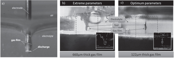
Figure 7. (a) Formation of gas film during ECDM [104]. Reprinted from [104], Copyright (2015), with permission from Elsevier, gas film thickness for (b) extreme parameters. Reprinted from [76], Copyright (2018), with permission from Elsevier and (c) optimum parameters [76]. Reprinted from [76], Copyright (2018), with permission from Elsevier.
Download figure:
Standard image High-resolution imageSurfactant mixed electrolytes have a significant effect on gas film characteristics in the ECDM process. Result shows that the gas film thickness decreases in the presence of surfactant, which reduces the critical voltage [71]. Jiang et al [104] have also concluded that using surfactants can reduce the surface tension of electrolyte and thereby reduces the gas film thickness. A study on gas film characterization shows that lower electrochemical activity is better for forming thinner gas films. Higher electrolyte concentration and higher electrolyte levels causes bigger hydrogen bubbles which leads to the formation of the thicker gas film [76]. Gas films formed at extreme and optimum process parameters to obtain minimum overcut, taper, and machining time are shown in figures 7(b)) and (c), respectively. Thinner gas film is better for stable discharge and uniform machining. Maintaining optimum IEG and tool-substrate gap leads to formation of a thinner gas film.
4.5. Tool electrode
Tool electrode has a significant influence on the machining performance in an ECDM process. Tool material, shape, conductivity, rotation, and polarity are some of the important parameters to consider about the tool electrode.
4.5.1. Tool material
A study by Mousa et al [105] shows that tool electrodes with higher thermal conductivity gives slower machining speed. According to the authors, an increase in thermal conductivity leads to an increase in the thermal energy transferred to electrolyte, leaving lesser thermal energy for micro-drilling. A comparative study using brass, copper, and tungsten proves this, with brass giving highest MRR. Reduction in MRR, while increasing pulse off time, have been found least in brass tool. Due to lower conductivity of brass, less heat is dissipated from tool [88]. Electrical conductivity of tool material affects characteristics of machined surface. Higher electrical conductivity produces more hydrogen bubbles and thinner gas film. Stable discharge and lower HAZ have been formed with molybdenum tool when compared with high carbon steel tool [106]. Different tool materials have different effects on machining which is summarized in table 4.
Table 4. Effect of tool material on machining.
| References | Material | Influence on machining |
|---|---|---|
| [88] | Brass | High thermal conductivity gives high MRR |
| [88, 105] | Copper |
|
| [105] | Tungsten |
|
| [106] | Molybdenum | High electrical conductivity causes rapid gas generation, and forms thinner gas film which gives rise to stable discharges. |
| [28] | Tungsten carbide | Lowest tool wear and good machining stability. |
| [28] | Stainless steel | The machinability is less than that of tungsten due to poorer surface finish. |
| [92] | Hardened steel | Hardened steel used to machine SiC reinforced composites with good MRR and low taper. |
4.5.2. Tool surface roughness
The surface roughness of the tool electrode has influence on machining during an ECDM process. The surface roughness affects the tool electrode's wettability and the gas film's formation. Higher surface roughness leads to formation of bigger gas bubbles due to the poor wettability and thereby forms a thicker gas film. Thicker gas film produces holes with larger overcut [28] and HAZ width [5]. The sparking activity of a smooth and textured tool surface is different. Uniform distribution of sparks has been observed on a surface textured tool. The microtexture enhances the spark frequency [29].
An abrasive tool can be used to obtain deeper holes compared to standard electrodes. The abrasives provide cutting action along with ECDM process. Since the abrasive particles are insulating in nature, they reduce side sparking and improve dimensional accuracy [53]. Singh et al [66] explored the effects of surface textured wire in TW-ECDM process. Spark discharges from entire surface of wire have been observed in case of textured wire due to localized electric field intensification.
In a smooth textured wire, maximum spark intensity observed at edges of wire, and spark discharges observed only at lower edges of the wire. If machining is done with a smooth-surfaced tool electrode, the machined surface will have the least amount of HAZ and overcut.
4.5.3. Tool wear
Tool wear is a critical factor to be considered during an ECDM process as it hugely affects the machined dimensions. The shape accuracy is affected due to tool wear as the wear causes length of tool to reduce continuously. Tool wear in ECDM is lower than that in EDM. This is due to enlargement of machined holes by electrochemical action and reduction of electric discharges in the side wall [17]. Yin et al [57] studied tool wear with electrolytes of different conductivity. When the electrolyte conductivity increases, the tool wear reduces. This is due to electrode position enhancement at higher conductivity. Another study compared tool wear of steel, stainless steel, and tungsten. They found tungsten have maximum tool wear and stainless-steel minimum [107]. Tungsten carbide has good machinability than stainless steel, but also has higher tool wear [28]. The tool wear observed for different materials is shown in figure 8. Materials like brass with low melting temperature shows higher tool wear as the cathode reaches very high temperature during ECDM process [108]. The tool wear rate is high for low feed rates due to longer exposure to electrolyte. In case of multi-tip electrodes, the tool wear is higher for corner tips because of the presence of fresh electrolytes. Lower tool wear has been found on central tips of a multi-tip electrode [109].
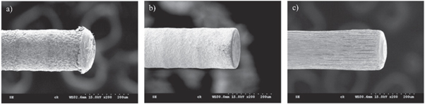
Figure 8. Tool wear in (a) stainless steel, (b) tungsten carbide, and (c) tungsten tool electrodes while machining quartz [28]. Reprinted from [28], Copyright (2010), with permission from Elsevier.
Download figure:
Standard image High-resolution imageMaterials with a low melting point can be used for short-duration machining, as very high temperature cannot be attained. Tool wear should be kept minimum to attain good repeatability in ECDM process. High melting point materials must be used for long duration machining, so that the tool wear will be minimum and process can have good repeatability.
4.5.4. Tool feed mechanism
Tool feeding technique and tool feed rates are major process parameters that influence the machining in an ECDM process. Various tool feeding techniques have been employed by different researchers. R Wuthrich et al [110] used gravity feed in the ECDM process for micro-hole drilling. In the gravity feed technique, the tool is always in contact with the workpiece, and a constant force is applied to the tool. The force should be maintained at a level that does not cause bending or breaking of the tool electrode. Rajput et al [12] used the adaptive tool feed for machining micro-holes in soda lime glass. In the adaptive tool feed technique, the feed rate is monitored with respect to the material removal rate and varied accordingly. Adaptive tool feed reduces tool-to-workpiece contact and enhances the formation of the gas film. Sharma et al [7] studied the effect of combined pulse feed approach in machining deeper micro-holes. In this approach, the feed rate and pulse frequency are reduced in different stages as the machining continues and the hole gets deeper. The counter-resistant feeding method is a drilling technique with a decreased force exerted on the workpiece. The counter-resistant feeding method gives higher repeatability as compared to the gravity feed technique [111]. In on-pressurized approach, constant mechanical pressure is maintained between the tool and the workpiece electrodes by giving a pressurized feed to the workpiece [83]. Wuthrich et al [112] studied the constant velocity feed method for drilling micro-holes in soda lime glass. In the constant velocity feed method, the tool is fed at a constant rate, and the force exerted on the tool is recorded simultaneously. The feed is paused when the force exceeds a pre-set threshold and is resumed when the force is negligible. Each tool feed technique has its own benefits and drawbacks which are outlined in table 5.
Table 5. Classification of different tool feed techniques.
| References | Tool feed technique | Principle | Benefits | Drawbacks |
|---|---|---|---|---|
| [110] | Gravity feed | The tool is always in contact with the workpiece, and a constant force is applied to the tool. | No additional setup is required for tool feeding. | Possibility of tool bending and breaking. |
| [12] | Adaptive tool feed | The feed rate is monitored with respect to the material removal rate and varied accordingly. | Improved geometrical accuracy of the micro-holes. | Lower material removal rate. |
| [7] | Combined pulse feed | The feed rate and pulse frequency are reduced in different stages as the machining continues and the hole gets deeper. | Reduces the machining time. | A low feed rate must be followed to prevent tool and workpiece contact. |
| [111] | Counter-resistant feed | Drilling with a decreased force exerted on the workpiece. | Higher repeatability is attained. | Possibility of tool bending. |
| [83] | On pressurized feeding | Constant mechanical pressure is maintained between the tool and the workpiece electrodes by giving a pressurized feed to the workpiece. | Reduces the critical voltage and provides high-frequency consistent discharges. | An increase in the exerted pressure can cause a fracture in the workpiece. |
| [112] | Constant velocity feed | The tool is fed at a constant rate, and the force exerted on the tool is recorded simultaneously. The feed is paused when the force exceeds a pre-set threshold and is resumed when the force is negligible. | Can machine micro-holes of diameter above 200 μm with non-pronounced surface cracks and homogeneous surface. | Need additional sensors for force measurement. |
4.5.5. Tool rotation
The tool rotation increases the electrolyte circulation in the machining zone and enhance the availability of fresh electrolyte. Tool rotation affects the surface roughness, hole diameter, and tool wear rate. It is noted that at higher tool electrode speeds, the surface roughness decreases. This is due to enhanced electrochemical machining as more fresh electrolyte is available [113]. The tool electrode rotation improves the centrifugal force and increases insulating property of gas film. This reduces the current density and tool electrode wear. Higher electrode rotating speed has been found to give better heat dissipation [114]. Liu et al [27] studied the variation in side gap with tool rotating speed. They found that increase in rotation speed leads to a decrease in side gap. At a very high rotation speed of 15,000 rpm, the stability of machining is reduced because no stable gas film is formed. Additionally, tools can break too. Tool rotation is a useful parameter to increase electrolyte circulation. It makes deep hole machining more effective.
4.5.6. Tool shape
The shape of tool electrode changes the electrolyte movement along with change in shape of cavity. Tool electrode with flutes on surface gives better electrolyte flushing than normal cylindrical electrode [90]. Hollow tool electrodes are used to inject electrolyte directly into machining zone. This facilitates effective deep-hole drilling by keeping steady electric discharge [73]. Zhang et al [115] conducted ECDM on DZ125L superalloy using a brass tool with varying inner diameters and shapes. Figure 9 shows the tool electrodes they used. A central residual cylinder remained in the machined micro-hole after machining in case of a single hole tool. The size of residual cylinder was reduced while using double hole tool electrode. Multiple hole tool electrodes were used to eliminate residual cylinder from the machined micro-hole. The hole was free of residual cylinder when a multihole tool electrode was used. Tool shapes are altered to enhance the flow of electrolytes.

Figure 9. Tool electrodes with different inner shapes [115]. Reprinted from [115], Copyright (2016), with permission from Elsevier.
Download figure:
Standard image High-resolution imageA spherical tool has less surface area in contact with the workpiece. Additionally, it enhances electrolyte flow [40]. A study on different tool tip shapes were conducted by Battacharyya et al [49]They used a straight side wall flat front tool, a taper side wall flat front tool, and a taper side wall-curvature front tool. tools with taper shows enhanced sparking action as compared to cylindrical tools. This is attributed to increased availability of electrolyte in the machining zone.
The use of batch or array tools in ECDM are also reported. Skrabalak et al [116] used batch electrode with nine squares of working tip. They found that the tool wear was lesser because of better electrolyte flushing.
5. Process parameter optimization
Figure 10 shows cause and effect diagram of input and response parameters in ECDM. Various studies have been conducted to find the optimum machining conditions for ECDM process. Grey relational analysis (GRA) was used to optimize ECDM process for MRR, average surface roughness, kerf width, and HAZ [21, 86, 117]. Analysis of means (ANOM) technique was utilized to get optimum parameters for reducing overcut and maximizing MRR and depth of cut [93]. Rajput et al [118] utilized response surface methodology (RSM) to optimize parameters for obtaining maximum MRR and minimum TWR. Taguchi's L9 orthogonal array was used by Tyagi et al [119] to maximize MRR. Optimized parameters and optimization techniques used by various authors are summarized in table 6.
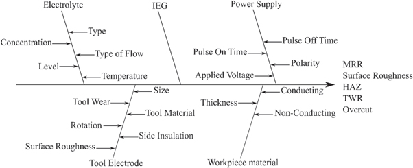
Figure 10. Cause and effect diagram of ECDM process.
Download figure:
Standard image High-resolution imageTable 6. Optimum input parameters found by different researchers and the optimization techniques used.
| References | Tool | Workpiece | Electrolyte | Optimum input parameters | Objective parameter | Optimization technique |
|---|---|---|---|---|---|---|
| [21] | Stainless steel | Silicon nitride | NaOH | V–50 V, EC –10 wt%, TON–0.002 s, | MRR, ASR | GRA |
| [86] | Stainless steel | Quartz | NaOH | V–35 V, EC–15 wt%, IEG–25 mm | MRR, HAZ | GRA |
| [117] | Brass wire (TW-ECDM) | Pyrex glass | NaOH | V–70 V, EC–200 g L−1, TON−500 μs, TOFF−450 μs, WFR–2.4 m min−1 | MRR, ASR, KW | Modified GRA |
| [93] | Tungsten carbide wire (TW-ECDM) | Silica glass | NaOH | V–55 V, EC–17 wt%, IEG–0.5mm, TON − 60 μs | MRR, MD, OC | ANOM |
| [118] | Stainless steel | Soda-lime glass | NaOH | V–50 V, EC–25 wt%, TFR–4 mm min−1, IEG–42.35 mm | MRR, TWR | RSM |
| [119] | Copper | Tempered glass | NaCl | V–80 V, EC–30 wt%, DC–80% | MRR | Taguchi's L9 orthogonal array |
V—Applied voltage, EC—Electrolyte concentration, TON—Pulse on time, TOFF—Pulse off time, ASR—Average surface roughness, WFR—Wire feed rate, KW—Kerf width, IEG—Inter electrode gap, MD—Machining depth, OC—Overcut, TFR—Tool feed rate, TWR—Tool wear rate, DC—Duty cycle, GRA—Grey Relational Analysis, ANOM—Analysis of Means, RSM—Response Surface Methodology.
6. Variants of ECDM
Numerous variations of ECDM have been studied to enhance the machinability and quality of machining. TW-ECDM is the most popular and researched variant of ECDM. Use of ultrasonic vibration and magnetic field have been also studied by many researchers.
6.1. Traveling wire ECDM
Traveling wire (TW-ECDM) or wire ECDM is a variant of ECDM in which the tool electrode is a thin wire. A schematic diagram of TW-ECDM is shown in figure 11. Brass and tungsten are commonly used materials for wire. One of the initial studies in TW-ECDM was by Jain et al [18], where they machined glass-epoxy and kevlar-epoxy composite using a brass wire. The effect of parameters on machining efficiency was found to be similar to normal ECDM. MRR increases with an increase in voltage and electrolyte concentration. Slicing of metal matrix composites was successfully completed using TW-ECDM [120]. The input condition of higher current and electrolyte concentration enhances electrochemical activity, giving better MRR [121]. It has been observed that overcut also increases along with MRR at higher voltages. To obtain good results, it has been suggested to conduct machining at lower voltages [122]. Overcut can also be reduced by increasing wire feed rate [123]. An increase in wire feed rate also increases MRR due to presence of fresh wire in the cutting zone. Width at beginning of cutting found always higher than the width during continuous cutting [124]. A study on machining of silicon dioxide epoxy nanocomposite by TW-ECDM reveals that MRR reduces with an increase in silica concentration in the workpiece [125].
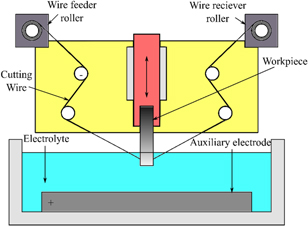
Figure 11. Schematic diagram of Wire ECDM.
Download figure:
Standard image High-resolution imageCoated wires have less chance of breaking during machining. TW-ECDM using a zinc-coated brass wire shows improvement in cutting speed and surface finish [126, 127]. Wire coated with abrasive materials like tungsten carbide [128] or diamond [129] adds sawing effect to TW-ECDM. The coated wires improve MRR and reduce kerf width. Machining of alumina can be done using diamond-coated wire without formation of any recast layer [98]. Table 7 concludes the results of various authors on TW-ECDM.
Table 7. Summary of studies on TW-ECDM.
| References | Tool | Workpiece | Electrolyte | Parameters | Remarks |
|---|---|---|---|---|---|
| [18] | Brass wire | glass-epoxy, kevlar-epoxy composite | NaOH | V = 55–70 V, and EC = 5–25 wt% | Better machining accuracy is obtained at lower voltage and electrolyte concentration |
| [120] | Copper wire, tempered stainless steel wire | Optical glass, quartz | KOH | V = 50–80 V, and f = 200–400 Hz | A higher voltage of around 75 V, and a lower duty factor of 0.3 gives better slicing. |
| [121] | Molybdenum wire | Al2O3 particle-reinforced aluminum alloy 6061 | Water based emulsion | V = 60–100 V, PD = 4–32 μs, and I = 0.5–3 A | Higher voltage may not give higher MRR as ceramic debris will hinder the machining |
| [128] | Stainless steel wire with WC layer | Silica glass | NaNO3 | V = 70 V, WFR = Increasing from 0 to 0.8 m s−1 in 3.4s | Better MRR was obtained because of a combination of ECDM and wire sawing |
| [130] | Brass wire | Borosilicate glass | NaOH | V = 45–55 V, EC = 150–250 g L−1, and WFR = 1.8–3 m min−1 | The hybrid methodology improves MRR by 46% than Taguchi methodology |
| [122] | Brass wire | Hylam-based fibre reinforced composites | KOH | V = 30–50 V, EC = 10–30 wt%, f = 55–95 Hz, WFR = 50–300 mm min−1, and TON = 50%–70% |
|
| [124] | Brass wire | e-glass fibre epoxy composite | NaOH | V = 40–70 V, EC = 50–200 g L−1, WFR = 0.15–0.3 m min−1, I = 1.4–2 A | The width of the micro-slice is slightly higher in the beginning than during the continuous cutting. |
| [129] | Diamond coated wire with steel core | Glass | NaCl | V = 58 V, and WFR = 1400 mm s−1 |
|
| [98] | Diamond coated wire with steel core | Alumina | NaCl | V = 52–58 V, and WFR = 700 mm s−1 | Diamond wire sawing combined with ECDM causes spalling of alumina without formation of any recast layer. |
| [126] | Zinc-coated brass wire | Quartz | V = 30–40 V, EC = 25–35 wt%, and WFR = 3–13 m min−1 | Coated wire improves cutting speed, MRR, surface roughness and lower kerf width. | |
| [125] | Brass wire | Silica epoxy nanocomposite | NaOH | V = 40–50 V, EC = 200–300 g L−1, TON = 300–400 μs and WFR = 1.7–2.5 m min−1 |
|
| [127] | Zinc-layered brass wire | Quartz | V = 36–45 V, EC = 35–45 g L−1, and WFR = 2–12 m min−1 |
| |
| [131] | — | Al6063/SiC/10p MMC | NaOH | V = 30–50 V, mist flow rate = 11–23 l min−1 |
|
| [123] | — | SiC Reinforced Z-Pinned Polymer Matrix Composite | NaOH | V = 25–35 V, WFR = 0.5–1 m min−1, and DC = 60%–80% |
|
V = Voltage, EC = Electrolyte concentration, f = Frequency, PD = Pulse duration, I = Current, WFR = Wire feed rate, TON = Pulse on time, DC = Duty cycle
6.2. Ultrasonic-assisted ECDM
Ultrasonic-assisted ECDM (UA-ECDM) is the application of ultrasonic vibration in ECDM, which has shown improvements in machining. A schematic of UA-ECDM is figure 12. Han et al [132] investigated the advantages of using ultrasonic-vibrated electrolyte in improving efficiency of ECDM process. The ultrasonic-vibration causes waves in electrolyte which increases the actual tool immersion length. An improvement in electrode reaction and current efficiency have been also observed due to electrolyte replenishment. This enhances the electrochemical action of the process. The results of another study where ultrasonic vibrations have been given to workpiece shows that the ultrasonic vibration is not enough to produce discharge in deep hole machining. The use of ultrasonic vibration improves surface integrity but reduces the MRR [23]. When applied to the tool electrode, ultrasound vibration provides better machining compared to normal ECDM. The gas film in UA-ECDM is thinner than in ECDM, increasing the discharge frequency. Higher discharge frequency in UA-ECDM leads to higher MRR [42, 81] and better depth of penetration [133]. The application of ultrasonic vibration is mainly focused on improving electrolyte circulation. It is effective only when applied to electrolyte or tool electrode. Using ultrasonic vibration on the workpiece did not result in any improvements.
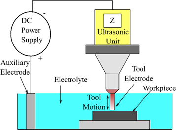
Figure 12. Schematic diagram of Ultrasonic Assisted ECDM.
Download figure:
Standard image High-resolution image6.3. LASER-assisted ECDM
Laser-assisted ECDM is a hybridization aimed to enhance the process capability of ECDM using a laser beam as an additional energy source. Research has been done using laser and ECDM simultaneously by Singh et al [43] in which Nd:YAG laser was focused in the vicinity of tool electrode to enhance the electrochemical reaction. The schematic diagram of laser assisted ECDM is shown in figure 13. The temperature of electrolyte was also increased by the laser source. This led to formation of thinner and stable gas film. Stable gas film and high energy due to laser, created a better quality surface with minimum damage. 10% reduction in overcut and tapering was obtained with laser assistance when compared with normal ECDM. Zhao et al [134] used the laser and ECDM separately to enhance quality of machined surfaces. They used two methods of machining, ECDM pre-process, and laser pre-process. In the ECDM pre-process, a micro-groove was first machined using ECDM alone, and laser machining was conducted on the same micro-groove. The protrusions at bottom of micro-groove created by ECDM is easily removed by laser without formation of any HAZ. The laser pre-processing is reverse of ECDM pre-processing. The micro-grooves formed by laser aid in formation of thin gas films during ECDM post-processing. Reduction in tapering and overcut is obtained in laser pre-processing. Utilizing laser assistance has several benefits. The electrochemical activity enhances by raising the electrolyte's temperature. Surface quality enhances, and the MRR rises in laser-assisted ECDM.
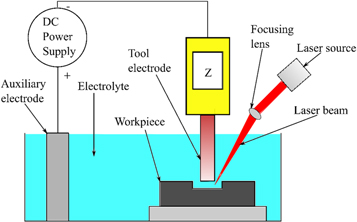
Figure 13. Schematic diagram of Laser-assisted ECDM.
Download figure:
Standard image High-resolution image6.4. Grinding-aided ECDM
The grinding-aided ECDM (G-ECDM) is useful in smoothening the rough surface generated in ECDM machining. The G-ECDM technique has combined action of electric discharge, electrochemical dissolution, and mechanical grinding. A schematic diagram of G-ECDM is shown in figure 14. A study using a hollow iron tool with a coating of diamond abrasive particles was conducted to machine particulate reinforced aluminum alloy 6061. The grinding effect removed the recast layer, enhancing surface quality, and MRR [41]. Ladeesh et al [135] utilized a diamond core drill as a tool electrode to machine soda-lime glass workpiece by G-ECDM technique. During machining, the discharges soften the workpiece, and grinding action removes it. The G-ECDM technique produces perfect holes at high MRR, low overcut, and low surface roughness. A drawback of this technique is edge chipping on hole exit. G-ECDM can also remove convex effect and produce perfect hole in MMCs [136].
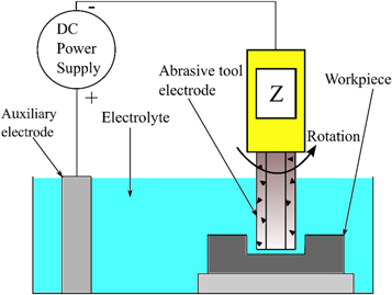
Figure 14. Schematic diagram of Grinding aided ECDM.
Download figure:
Standard image High-resolution imageIn grinding-assisted ECDM, material removal is initially done by ECDM technique. The machined features are then machined again using a grinding tool. The ECDM provides higher MRR and PCD grinding improves surface quality. The hybrid process reduces machining time by 30% compared to conventional grinding [4]. G-ECDM could be employed when a very high surface finish is necessary. The overall machining time could also be decreased.
6.5. Magnetic field assisted ECDM
In Magnetic Field assisted ECDM (MF-ECDM), magnetic field is used to enhance the efficiency of electrolysis. When the electric field is perpendicular to magnetic field, the Lorenz force drives ions in the electrolyte into motion and induces a magnetohydrodynamic (MHD) convection. Figure 15 displays a schematic diagram of the MF-ECDM. This creates a stirring action, improving electrolyte circulation. A comparative study using non-magnetic and upward as well as downward magnetic fields was conducted. They observed the effects of magnetic field on electrolyte circulation and gas film formation. The electrolyte circulation was found to improve due to MHD convection. There was no effect of magnetic field on gas film [24]. Application of magnetic field did not affect the tool wear rate [137].
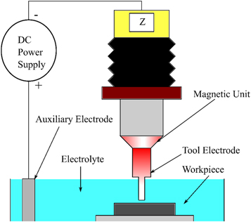
Figure 15. Schematic diagram of Magnetic assisted ECDM.
Download figure:
Standard image High-resolution imageThe effect of MHD convection was also studied on TW-ECDM. Similar results have been obtained where the MHD convection improves electrolyte circulation leading to better MRR [25]. The enhanced electrolyte circulation improves removal of debris from machining zone developing straight surface with less surface roughness [138, 139]. Better removal of debris and more bubbles from electrolysis led to reduction in discharge current and uniform sparking [140]. Improvements in electrolyte circulation have been observed after the application of a magnetic field. Increased electrolyte circulation has a significant positive impact on electrochemical action.
7. Applications
The ECDM process has been widely studied to machine microstructures on conducting [141, 142] and non-conducting materials [143] for application in micro electromechanical systems. A study on micro-hole machining of borosilicate glass was conducted by Yang et al [34]. They observed that ECDM gives better MRR and surface roughness compared to laser drilling. Higher MRR was obtained with electrolytes of higher PH values. Straightness accuracy of tool electrode enhances circularity of micro-hole [144]. An oscillating tool improves MRR and depth of cut during drilling operation because of better electrolyte circulation [145]. Alternately, the use of drill bit as a tool electrode provides better electrolyte circulation than a cylindrical tool electrode [90].
Micro-drilling of ceramic-coated Ni-superalloy was successfully conducted using tungsten carbide as a tool electrode. Figures 16 and 17 shows the effect of ECDM on ceramic coating and Nickel (Ni) substrate, respectively. ECDM discharges did not cause any cracks or damage bonding between the layers. They observed that both electric and electrochemical discharge occurs only while machining Ni substrate. While machining ceramic coating, only electric discharge occurs [146]. Drilled holes are free of recast layer as it is removed by electrochemical action [99]. As shown in figure 18, micro-hole arrays can be machined using multi-tip array tools, which is faster than single-tip tools [97, 109].
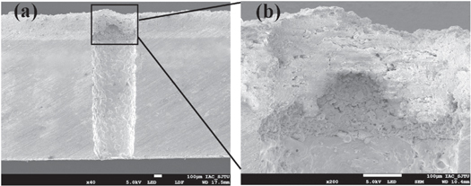
Figure 16. (a) section view of through hole, (b) Details of sidewall surface of coating layer machined by ECDM [146]. Reprinted from [146], Copyright (2018), with permission from Elsevier.
Download figure:
Standard image High-resolution image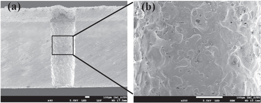
Figure 17. (a) The section view of through hole, (b) Details of sidewall surface of superalloy substrate machined by ECDM [146]. Reprinted from [146], Copyright (2018), with permission from Elsevier.
Download figure:
Standard image High-resolution image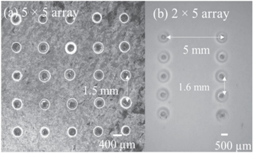
Figure 18. Optical images of micro-hole array of (a) 5 × 5 and (b) 2 × 5 micro-holes machined at optimum process parameters [97]. Reproduced with permission from [97]. CC BY-NC-ND 4.0.
Download figure:
Standard image High-resolution imageMicro-channel machining for biomedical and micro-fluidic applications can be done using ECDM technique in different kinds of materials. As already discussed, applied voltage and electrolyte concentration has a major effect on material removal [147, 148]. Jain et al [14] machined micro-channels on quartz with a minimum channel width of 144 μm. They found the depth of channel reduces in the direction of machining, which is due to tool electrode wear. Improvement in MRR is obtained by increasing electrolyte temperature, but very high temperatures may cause thermal cracking of workpiece surface [82]. Deeper micro-channels can be machined using a side-insulated tool, as it reduces side sparking and concentrate heat transfer to tool tip [149]. ECDM can create micro-channels on PDMS at lower cost and in less time than lithography with a slight increase in surface roughness [78]. Varying the electrolyte concentration changes surface texture of micro-channel. Lower concentrations create a branched feathery-like structure and higher concentrations create a smooth texture, as shown in figure 19 [63]. While machining micro-channels on borosilicate glass, the channel width has been found approximately same as tool width [150]. Tool wear can lead to non-uniform channel dimensions [151]. Channels machined using KOH as electrolyte has lower width and clear edges than channels machined using NaOH [91].
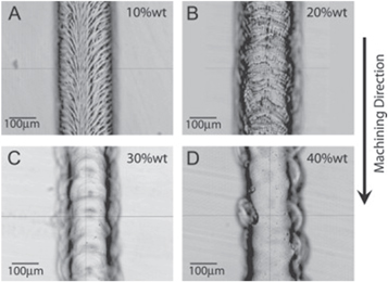
Figure 19. Channels machined at different concentrations of NaOH [63]. Reprinted from [63], Copyright (2012), with permission from Elsevier
Download figure:
Standard image High-resolution imageMachining of microstructures in quartz was exhibited by Nguyen et al [13] using a tungsten carbide alloy tool. Machining was done in two stages, initial rough cutting and final finishing step. Table 8 depicts how ECDM has developed over the years in machining different materials.
Table 8. Progress in applications of ECDM over the years.
| References | Year | Tool | Workpiece | Electrolyte | Process | Remarks |
|---|---|---|---|---|---|---|
| [152] | 1995 | Tungsten | Quartz glass | NaOH, KOH, HCl | ECDM | Successful drilling of through holes |
| [153] | 1996 | Brass wire | Piezoelectric ceramic, carbon fibre reinforced composite | NaOH | TW-ECDM |
|
| [34] | 2001 | Tungsten | Borosilicate glass | NaOH, KOH | ECDM |
|
| [53] | 2007 | Diamond embedded tool | Sintered Al2O3 | NaOH + KOH | ECDM with abrasive electrode | Machine large size holes using smaller tool electrode, and also deeper holes. |
| [26] | 2007 | Tungsten carbide | Borosilicate glass | NaOH with graphite powder | ECDM with powder mixed electrolyte |
|
| [23] | 2012 | Tungsten | Soda-lime glass | NaCl | Ultrasonic assisted ECDM | Application of ultrasonic vibration enhanced surface integrity, and depth of machining. |
| [41] | 2013 | Iron based tool with diamond particles | Particulate reinforced aluminum alloy 6061 | NaNO3 | Grinding aided ECDM | Up to 10 times improvement in surface roughness on comparison with normal ECDM |
| [71] | 2017 | Tungsten carbide | Soda lime glass | SDS, C-TAB mixed KOH and NaOH | ECDM with surfactant mixed electrolyte |
|
| [25] | 2017 | Brass wire | Quartz | NaOH | Magnetic field-assisted TW-ECDM |
|
| [70] | 2020 | Tungsten carbide | Soda lime glass | NaOH | ECDM with nano electrolyte |
|
| [43] | 2020 | Tungsten carbide | Carbon fibre reinforced polymer composite | NaOH | LASER assisted ECDM |
|
8. Recent developments, challenges, and future scopes
The latest studies in ECDM have been focused on different variants of ECDM. Although TW-ECDM is the most researched variant of ECDM, UA-ECDM and MF-ECDM has gained importance. Studies on different tool feed techniques have been also reported. Recently, gas film formation and mechanism has been studied as an important parameter.
The ECDM process has been widely studied during the past decades. Even after these extensive studies, ECDM is not commercially used. It is due to the stochastic nature of the process and material removal. Gas film formation and its controlling has not been developed to a standard model. A pie chart showing amount of research conducted on various electrolytes is shown in figure 20. It is clear that very few studies on acidic electrolytes have been conducted. Electrolytes have corrosive nature, which can damage the machine. Fumes produced during machining are harmful to humans. Singh et al [154] reported presence of carcinogens in breathing zone during ECDM process. An alternative electrolyte, which is safe and environment friendly should be identified.
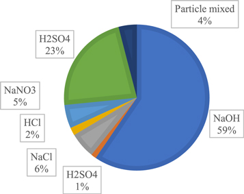
Figure 20. Research work done on different electrolytes.
Download figure:
Standard image High-resolution imageMost of the studies are focussed on enhancing MRR and surface quality of machining. More studies are required to find ways to reduce undesired effects like HAZ, overcut, and tapering. From figure 21, it is clear that most studies have concentrated on glass and its variants as the workpiece material. Machining of MMCs and ceramics should be explored for more acceptance of ECDM process.
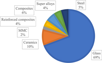
Figure 21. Research work done on different workpiece materials.
Download figure:
Standard image High-resolution imageTool materials which have been used in ECDM are depicted in figure 22. Tool wear is a major issue causing uneven machining and reducing repeatability of process. Tungsten and tungsten carbide shows very low tool wear among all the materials studied. Other materials like MMCs could also be considered as tool material.
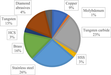
Figure 22. Research work done on different tool materials.
Download figure:
Standard image High-resolution imageHigh aspect ratio micromachining is required in optics [155], lab-on-chip [156], and other MEMS [157] devices. The capability of ECDM for high aspect ratio micromachining could lead to popularity of the process. Until now, the majority of works on ECDM have been focused on machining microholes. More research should be focused on machining microchannels, 3D micro-structures, and other complex geometries required in micro heat dissipation devices such as heat sinks, heat exchangers, etc More successful works creating above mentioned micro-features with more accuracy are necessary for the widespread acceptance of ECDM.
9. Conclusions
ECDM is an advanced machining process that overcomes the inability of conventional machining methods in micromachining of non-conducting materials. The research of numerous researchers over the previous few years is reviewed in this article. It is observed that applied voltage is the most influential parameter in ECDM, followed by electrolyte concentration. A thorough discussion of the input parameters and their influence on machining is presented.
Basic electrolytes have better performance than acidic and neutral electrolytes. Precautions must be taken against the toxic fumes of basic electrolytes while machining.
- Electrolyte concentration should be chosen based on application. Higher electrolyte concentration gives higher MRR and adverse effects like HAZ, overcut, and tapering.
- Electrolyte can be mixed with conductive particles like graphite or surfactants like SDS to modify electrolyte characteristics. Particles like graphite will enhance electrolyte conductivity. Surfactants will reduce the surface tension of electrolyte.
- Pressurized electrolyte flow through hollow tool electrodes can enhance deep hole drilling. Pressurized flow ensures electrolyte presence at deep holes while machining.
- A thinner gas film is better for stable discharges and uniform machining. Maintaining optimum IEG and tool-substrate gap leads to formation of thinner gas film.
- Materials with a low melting point can be used while machining for a short-duration as very high temperatures are not attained. Tool wear should be kept minimum to attain good repeatability in ECDM process as the shape of machined part is highly dependent on tool geometry.
- Providing tool rotation or using different tool shapes can enhance electrolyte circulation.
- Many variants of ECDM have shown better performance over the normal ECDM. UA-ECDM and MF-ECDM improves the electrolyte circulation, enabling enhanced performance in deep hole machining.
- G-ECDM can be used when a better surface finish is required.
- The ECDM process can be a suitable option for micromachining non-conducting materials. Commercial use of ECDM will be possible when efficient control of overcut, taper, and HAZ is possible.
Data availability statement
All data that support the findings of this study are included within the article (and any supplementary files).
Declaration of competing interest
There were no financial conflicts of interest or relationships between the study's authors that might influence their research.